- Welcome to YOCH Bearing!
- 0086-531-85866205
- 0086-16653196205
- market@yochibearing.com

How to improve IKO bearing reliability measures?

Which model is the bearing housing with SKF 3208A-Z bearing?
08/09/2022
What is the meaning of bearing DN value?
13/09/2022
This paper analyzes the function and working condition of IKO bearing in hydraulic torque converter of bulldozer, and puts forward special requirements on the design, manufacture, selection and installation process of bearing, which effectively improves the reliability and service life of the bearing.
Hydraulic torque converter; IKO bearings; reliability
How to improve the reliability of IKO bearings installed on TY320 torque converter is a key technical issue to prolong the service life of TY320 torque converter. TY320 type hydraulic torque converter is installed on the TY320 bulldozers are connected to the engine and gearbox transmission device, must be used for the specific structure of bulldozer and working condition, for in the use of the damage of bearing in carries on the analysis and research, in the design, manufacture, selection and installation of bearing technology and other aspects put forward special requirements, Only in this way can the reliability of IKO bearing be effectively improved and the service life of TY320 hydraulic torque converter be prolonged.
1. The role and working conditions of bearings
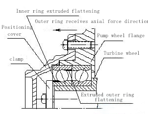
The IKO bearing on TY320 hydraulic torque converter is an angular contact ball bearing installed back-to-back in pairs (bearing rear code plus /DB). The inner ring of the bearing is installed on the turbine hub, and the outer ring is installed on the pump wheel contact plate. An important role of the bearing is axial positioning, that is, to ensure that there is a certain axial clearance between the pump wheel, turbine and regulating wheel of the hydraulic torque converter, so that the three wheels of the hydraulic torque converter do not collide and friction when working. If the bearings are damaged, there will be friction collision between the three wheels, and the hydraulic torque converter will not work properly.
The working temperature of this pair of bearings in the hydraulic torque converter is about 100℃. The inner and outer rings rotate with the turbine and pump wheel respectively, and the relative speed of the inner and outer rings changes frequently in a wide range. The working condition of bulldozer is earth-moving – backward – walking – earth-moving, so the axial load of bearing is also frequently changed. Especially in the earth pushing encountered large stones or roots, load suddenly increased, pump wheel with the engine speed unchanged, turbine speed rapidly decreased, torque rapidly increased, bearing inside and outside the ring of the relative speed will suddenly improve, and at the same time by a lot of axial impact load.
2. bearing damage and cause analysis
According to the inspection of several cases of bearing damage, it is found that in this pair of bearings installed back-to-back, as shown in FIG. 1, the left bearing is seriously damaged, the steel plate stamping cage is deformed and fractured, the ball surface is worn and deformed, and the shoulder of the inner and outer bearing raceway subjected to axial impact is extruded and flattened. This situation shows that the bearing is frequently subjected to a large unilateral axial impact load as shown in Figure 1, that is, the bulldozer is often overloaded. The right bearing is not damaged. This indicates that the preload amount of pairwise mounting bearings is inappropriate. In addition, check the lubricating oil containing more impurities, which from the ball and raceway surface there are many pitting phenomenon also reflects the oil is not clean. This shows that the lubricating oil filter maintenance is not in place.
The causes of bearing damage are complex. Bearings often work in high temperature, which will reduce the strength of bearings; The bulldozer frequently overloads the work so that the bearing is frequently subjected to great axial impact, resulting in plastic deformation and damage of the ball and raceway; Unclean lubricating oil will cause early wear of bearings. These reasons boil down to the excessive use and improper maintenance of the operator of the bulldozer, so that the bearing works for a long time in very bad conditions, all kinds of adverse effects on a bearing at the same time, resulting in the early damage of individual bearings. In order to reduce the failure rate of hydraulic torque converter to zero, special requirements for bearing design, manufacture, selection and installation process are formulated.
3. Special requirements for bearing design, manufacture and selection
In order to improve the reliability of these bearings under harsh working conditions, special requirements are put forward in the design, manufacture and selection of bearings:
3.1 Selection of docking antenna
IKO bearing is angular contact ball bearing, angular contact ball bearing can bear radial load and axial load at the same time, its axial load capacity is determined by the contact Angle, the greater the contact Angle, the greater the axial load capacity. Angular contact ball bearings have three kinds of contact Angle specifications, respectively 15°, 25° and 40°. The original TY320 hydraulic torque converter uses 25° contact Angle bearings. The 40° contact Angle bearings are suitable for bearing large axial loads, which should bear large axial impact loads when the bulldozer works under heavy load. So we chose 7215B/DB bearing with contact Angle of 40° instead. (Post code B indicates contact Angle of 40°)
3.2 Optimization design of inner ring
7215B/DB bearing inner raceway has two specifications. One is that the diameter of the shoulder on both sides of the inner raceway is the same. Since angular contact ball bearings can only withstand axial loads in one direction, the shoulder on one side of the inner raceway will not be subjected to axial loads, and the shoulder on the other side will not withstand large axial impact loads. After optimization design, in the case of the same weight, the diameter of the shoulder on both sides of the raceway of another specification is not the same, the shoulder diameter of the side that does not bear axial load decreases, and the shoulder diameter of the side that bears axial load increases, so that the bearing of this specification can bear greater axial impact load. So we choose the latter specifications of the optimized design of the inner ring.
3.3 Requirements on cage material and style
The mechanical stress of cage comes from friction force, stress force and inertia force, and is also eroded by some lubricants and their aging products, organic impurities and other chemical substances. Therefore, the selection of cage material has a great influence on the reliability of bearing operation. Because the bearings work at higher temperatures, phenolic laminates tubular solid cage or nylon cage cannot be used, and they are frequently subjected to large axial impact loads, so we choose 7215BM/DB bearings of brass solid cage. (Rear code M for brass solid cage). Due to the structure of different diameters on both sides of bearing inner and outer raceway, there is not much space left for cage. In order to strengthen the strength of the cage, the cage is designed as a ball-guided cone bench cage.
3.4 Determination of preload deformation δ
Installed in pairs of angular contact ball bearing is in bearing production has the size of the deformation, considering the preload on the match of the two bearing inner ring or outer ring on the end face of deformation of the delta, grinding to certain preload when install the bearing to the bearing parts, with a fastening device corresponding face pressure, two bearings in the preloaded state. See Figure 2.
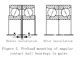
The purpose of bearing preloading is to increase the stiffness of the bearing; Make the rotation axis in the axial and radial direction correct positioning, improve the rotation accuracy of the axis; Reduce the vibration and noise of bearing parts; To prevent the rolling body rotation and rotation slip phenomenon; Increase the bearing internal load area, improve the rationality of bearing internal load distribution; Compensation of bearing internal clearance changes caused by wear; Reasonable pretightening can prevent vibration grain damage and reduce friction and wear; Extend bearing life.
However, if the preload deformation is too large, the friction torque will increase when the bearing works, leading to the overheating and service life of the bearing. Therefore, it is necessary to select the appropriate preload deformation amount according to the load situation and the use requirements, and determine the appropriate preload deformation amount through the test.
The amount of preloading deformation of the actual bearing in the four states of working state, installation state, natural state and manufacturing state is different. The increase of the temperature in the working state increases the preloading deformation, and the interference of the hole and shaft in the installation state also increases the preloading deformation. Therefore, the preloading deformation of the bearing in the manufacturing state is less than the preloading deformation in the working state. The amount of the preloading deformation is determined according to the temperature in the working state and the tolerance of the mounting hole and shaft. After actual installation and test operation, we have determined the most appropriate preload deformation.
4.Special requirements for the installation process of bearings
Improper operation in the installation process is an important hidden danger that causes the early damage of bearings. We also put forward special requirements in bearing installation process:
4.1 It is not allowed to install bearings by tapping. Bearings must be installed by pressing.
4.2 Bearings must be installed with special tooling designed by the push-in method.
4.3 When pressing into the bearing outer ring, the bore shoulder under the bearing hole of the pump wheel connection plate must be padded to prevent internal injury at the root of the bore shoulder when pressing to the bottom.
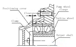
4.4 Before pressing into the inner ring, the clearance between the single positioning hood and the bearing end face shall meet the assembly process requirements, as shown in Figure 3.
4.5 Guide device must be used when pressing into the inner ring to prevent axial surface damage caused by pressure deviation.
4.6 The two bolts of the inner ring press plate must be tightened after the 36 bolts of the pump wheel and the pump wheel connecting plate are tightened.
4.7 After the installation, there is no abnormal friction feeling when rotating the wheel connection plate of the pump. When rotating relative to the output shaft, it can have a little pre-tightened connection feeling, and it cannot be bitten to death with the output shaft.